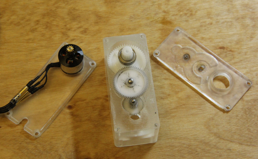
I’ve avoided 3D printing for as long as I can. Now that I’m away from a marvelous school machine shop, though, I thought I’d finally take the dive after some of the success that [JB] has been having with functional prints.
This project is a bit of an old hat. Since [JB] first pointed us to using servo replacement gears as mini-combat-robot transmissions, I’ve been dropping them into project after project whenever I need a little gear reduction. Compound gears–especially the kind that can take a bit of torque in small projects–are pretty annoying to source. This all-in-one set of servo replacement gears gives us a kit that works pretty well for many simple applications.
These replacement gears have a bit of magic “zen” in that the rest of the parts needed to work with them are all stock from McMaster-Carr. It just so happens that M2 and M3 dowel pins will slip-fit into the gear bores almost perfectly (the smaller bore needs to be hand-widened with a 2mm drill bit), and two metric bearings on the output gear enable smooth and high-speed output via the spline.
(For more details on actually doing something with that spline, see [JB’s] spline adapter post.)
All that remains is putting together a housing. The tricky part here is achieving about ±0.01″ (0.254mm) tolerances on the spacing between gears. These metric gears are module 0.4 and 0.5, the former of which is close to a 64-pitch (imperial) gear spacing. Because the gear pitch is so fine, putting together a DIY assembly becomes a tricky goldilocks scenario. If the spacing is too tight, the gears grind; too close and the gears wont mesh at all or skip teeth.
I was curious to see if the Form1+ could handle the spacing tolerances, and I was pleasantly surprised! After press-fitting the pins and loading up the bushings, bearings, and gears, the transmission runs smoothly. The print above is 3 pieces, each printed at 0.1mm resolution. The biggest piece containing the important pin press-fits was printed almost horizontally such that the internal weight of the part didn’t warp the x,y location of one hole relative to another. In that way, the holes were printed at the same time from the same layers.
I’ll post a video when I finally get the motor up and running. I’m imagining a similar setup for the remote control R.O.B. project I’m working on.
